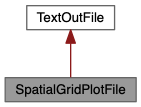
#include <SpatialGridPlotFile.hpp>

Public Member Functions | |
| SpatialGridPlotFile (const SimulationItem *item, string filename) | |
| void | writeCircle (double radius) |
| void | writeCube (double x1, double y1, double z1, double x2, double y2, double z2) |
| void | writeLine (double beg1, double beg2, double end1, double end2) |
| void | writeLine (double x1, double y1, double z1, double x2, double y2, double z2) |
| void | writePolyhedron (const vector< double > &coords, const vector< int > &indices) |
| void | writeRectangle (double min1, double min2, double max1, double max2) |
Additional Inherited Members | |
 Private Member Functions inherited from TextOutFile Private Member Functions inherited from TextOutFile | |
| TextOutFile (const SimulationItem *item, string filename, string description) | |
| ~TextOutFile () | |
| void | addColumn (string quantityDescription, string unitDescription=string(), char format='e', int precision=9) |
| void | close () |
| void | writeLine (string line) |
| template<typename... Values, typename = std::enable_if_t<CompileTimeUtils::isNumericArgList<Values...>()>> | |
| void | writeRow (Values... values) |
| void | writeRow (vector< double > values) |
 Private Attributes inherited from TextOutFile Private Attributes inherited from TextOutFile | |
| std::ofstream | _out |
| Units * | _units |
This class inherits from the TextOutFile class and is specifically used to write geometric information about a spatial grid to a data file in a text format that can be easily plotted. There are two format variations for 2D and 3D information, respectively. The 2D format describes the intersection of a spatial grid with one of the coordinate planes. The 3D format fully describes all or part of the spatial cells in the grid. Each line in the file contains two (2D) or three (3D) coordinates seperated by whitespace, or is empty. Consecutive nonempty lines represent a sequence of "lineto" commands; an empty line marks a "moveto" command.
| SpatialGridPlotFile::SpatialGridPlotFile | ( | const SimulationItem * | item, |
| string | filename | ||
| ) |
The constructor creates the output file with the specified name and sets the appropriate precision for the numerical values in the text file.
| void SpatialGridPlotFile::writeCircle | ( | double | radius | ) |
This function outputs a number of 2D line segments describing a circle with the specified radius, using the Units object specified in the constructor to convert the coordinates to output units.
| void SpatialGridPlotFile::writeCube | ( | double | x1, |
| double | y1, | ||
| double | z1, | ||
| double | x2, | ||
| double | y2, | ||
| double | z2 | ||
| ) |
This function outputs 3D line segments describing the specified cuboid, using the Units object specified in the constructor to convert the coordinates to output units.
| void SpatialGridPlotFile::writeLine | ( | double | beg1, |
| double | beg2, | ||
| double | end1, | ||
| double | end2 | ||
| ) |
This function outputs the specified 2D line segment, using the Units object specified in the constructor to convert the coordinates to output units.
| void SpatialGridPlotFile::writeLine | ( | double | x1, |
| double | y1, | ||
| double | z1, | ||
| double | x2, | ||
| double | y2, | ||
| double | z2 | ||
| ) |
This function outputs the specified 3D line segment, using the Units object specified in the constructor to convert the coordinates to output units.
| void SpatialGridPlotFile::writePolyhedron | ( | const vector< double > & | coords, |
| const vector< int > & | indices | ||
| ) |
This function outputs 3D line segments describing the specified polyhedron, using the Units object specified in the constructor to convert the coordinates to output units. Assuming the polyhedron has \(n\) vertices, the first vector contains the \(3n\) vertex coordinates as a sequence
\[x_0,y_0,z_0,x_1,y_1,z_1,...,x_{n-1},y_{n-1},y_{n-1}\]
The second vector contains the vertex indices for all polyhedron faces. Each vertex index is a number in the range \([0,n-1]\). The indices for each face are preceded by the number of vertices in the face. Assuming the polyhedron has \(k\) faces, the index sequence looks like
\[m_0,i_{0,0},i_{0,1},...,i_{0,m_0-1},...,m_k,i_{k-1,0},i_{k-1,1},...,i_{k-1,m_k-1}\]
| void SpatialGridPlotFile::writeRectangle | ( | double | min1, |
| double | min2, | ||
| double | max1, | ||
| double | max2 | ||
| ) |
This function outputs the 2D line segments describing the specified rectangle, using the Units object specified in the constructor to convert the coordinates to output units.